Write a program to output HSI clock on a microcontroller pin and measure it using oscilloscope or logic analyser.
Note that MCO is a signal internal of the MCU, which needs to be routed to an output pin on the MCU.
Procedure
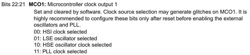
- Select desired clock for Microcontroller Clock Output (MCOx) signal
- To select HSI, we should ensure that it is selected in the MCO1 clock configuration register, but making sure those
- Examine the alternate function mapping table:
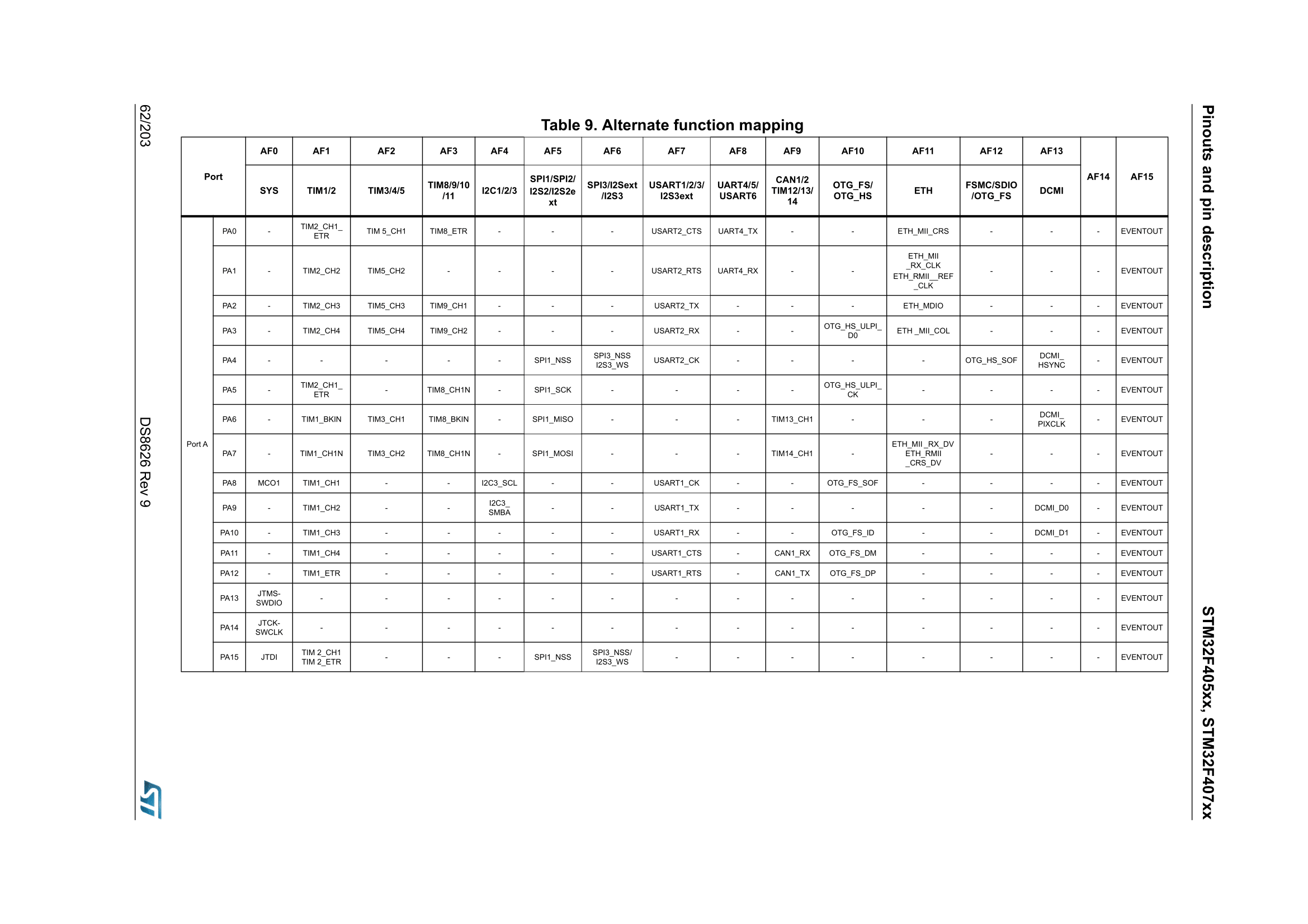 How to interpret the table:
- E.g. For GPIO Port A Pin 8 (PA8), if we set its mode to AF0, then this pin behaves as an MCO1 clock signal.
- Note that PA8 does not refer to the pin number; refer to the MCU schematic to determine this. PA8 - 67
- Output the MCOx signal on the MCU pin